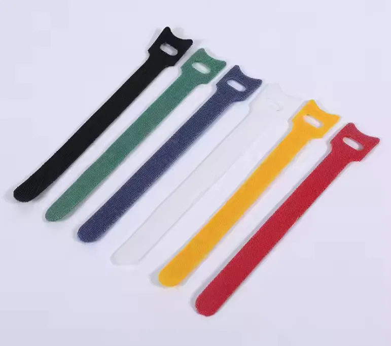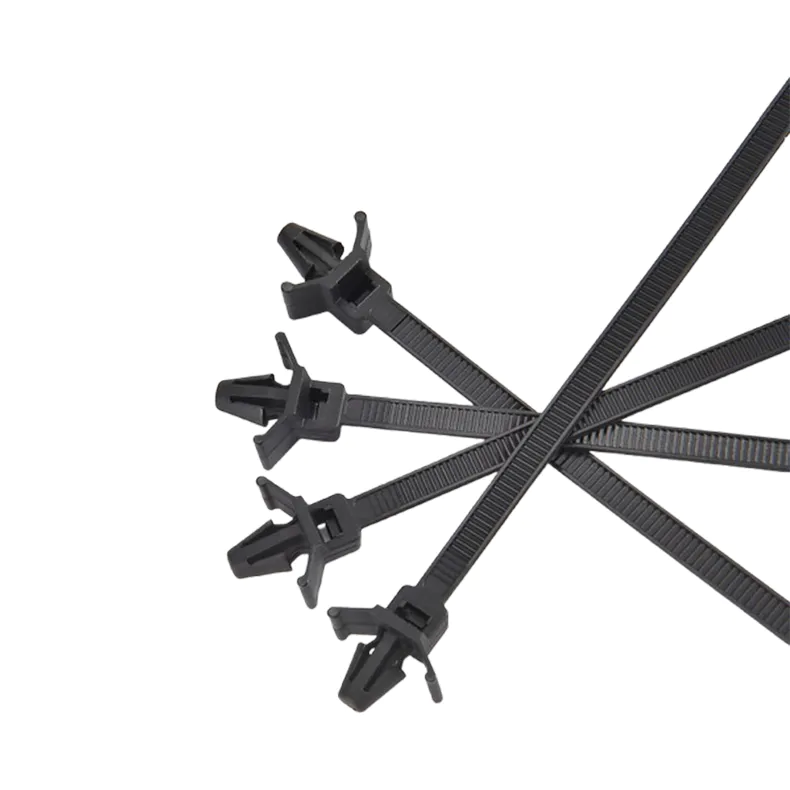
Self-locking nylon cable tie
Electrical Accessories
- Tape
- Terminals & connetors
- Cable Lug
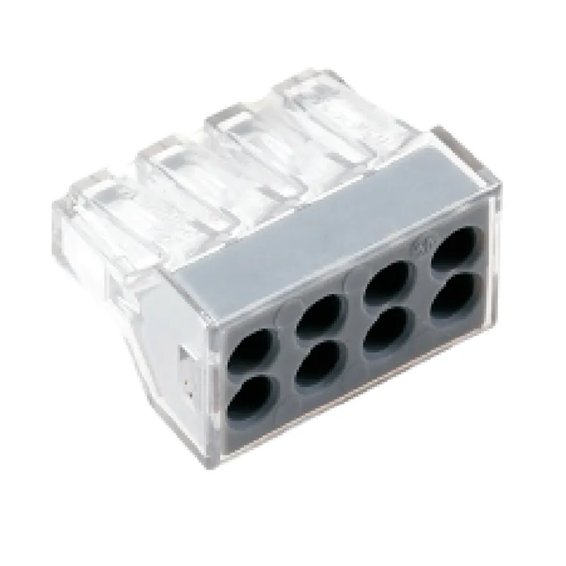
- Terminal block
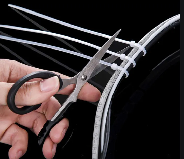
- Cable tie
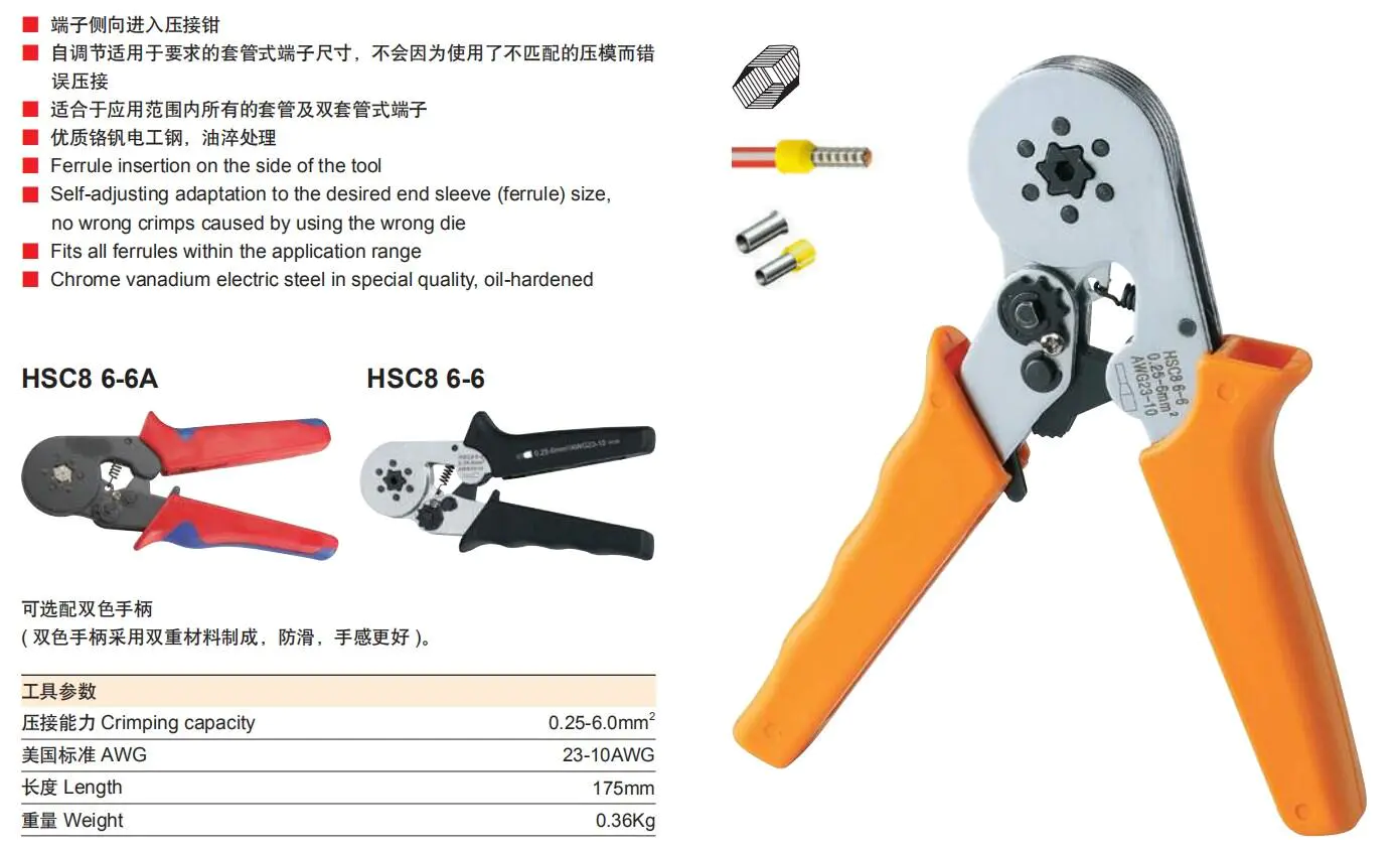
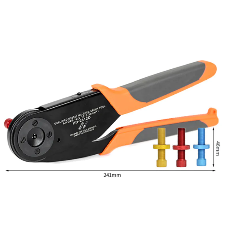
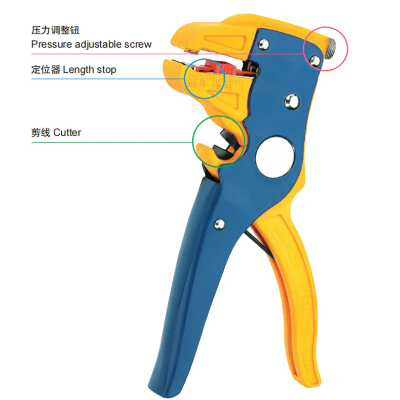
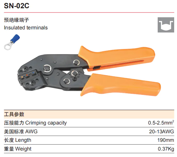
- Crimping tool
- Heat shrinkable tube
- Cable marker
- Junction box
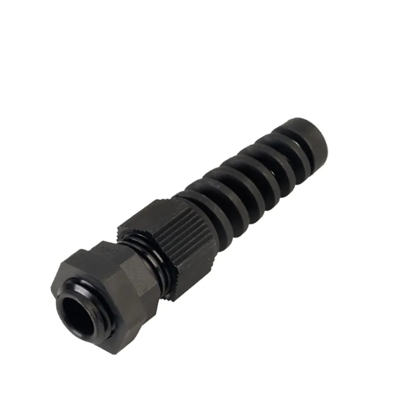
- Cable gland
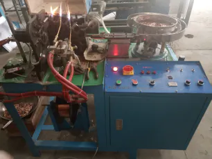
- Corrugated hose & spiral wrap band
- Wire duct
- Din rail
- Cable clips & mount
- Signal light
- Push button switch
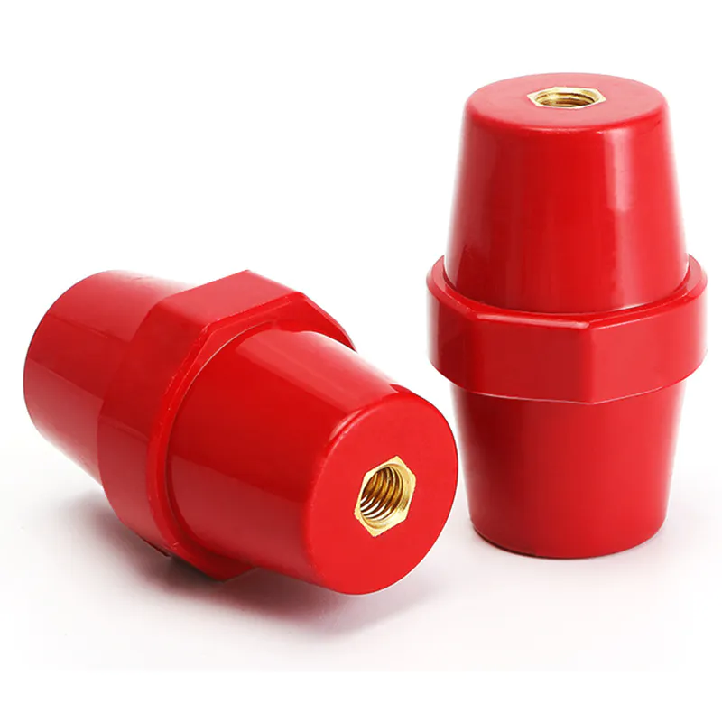
- Standoff insulator
- Pet braided sleeve
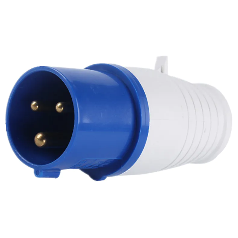
- Industrial plug & socket
- Auto fuse
- Others
led cube display
by:MKS
2020-03-04
In this project, you will build an 8x8 LED cube as a monitor.
After building the cube and learning the basics of the code, you will be able to write your own display animation.
This is a great visual for scientific purposes and it will be a great addition to the decor of your room!
In the process of the cube
Building, you will get a range of basic electronic technologies that pave the way for more complex projects in the future.
This is a personal project for my e-course and it took about five weeks.
I spend 12 hours a week on this project and I have access to parts and tools that are usually found in the university\'s electronics lab.
It may also be a good thing to know this, although the workload is not a cake or a hand
Professional knowledge is required.
Instead, you will get a lot of experience and lessons from your own mistakes.
Statement: I\'m from Kevin Darrah (
Who built the 8x8x8 RGB cube (
Three times the work! ).
The waveform display is my own job.
Before you start this project, I highly recommend watching all his LED videos!
They are very helpful in understanding how everything works, which is essential for this complex project!
I briefly explained the circuit and overall architecture when I talked about circuit connections and code, so can jump to this section first to get a theoretical understanding :)
First of all, test all LEDs!
I connected a circuit with an LED and a resistor of 100 ohms.
I then test one LED at a time and add it in parallel with the other.
We have to discard 1)broken LEDs, 2)
LEDs with anode and cathode backward (
You don\'t want to just \"remember\" which one flipped it! )3)dimmer LEDs.
Next, we made the wooden fixture, which is the last stand I made for the cube.
Drill a 1 inch 8x8 mesh between the center of the hole.
Select drill bits with a diameter just above the led diameter so that they can be installed into the hole and remain straight.
We nailed extra strips around to keep the surface of the board flat (
We made the board with plywood, so it has a lot of elasticity).
In addition, this improves the area with holes so that the led can pass through the holes.
Select one side and place two long nails on the same line as the center of the hole.
We tie the wires to these nails.
We can start the LED arrangement now!
I didn\'t find an effective way to make a straight line, so I only
Twist the wire off with wooden blocks.
Place the wire on the edge of the block;
Press and hold the wire on one side of the block with your thumb, and then pull the wire through;
The edge of the block will be canceled-kink the wire.
I recommend wearing gloves to protect your thumb:
Put 8 LEDs into this line, the long legs are the anode, facing in one direction.
We need to weld them to the wires.
Please note that the plane formed by the anode leg and the cathode leg should be perpendicular to the wire of the wire, and the cathode leg should be away from the wire.
Tie the wire to the nail and pull it through the LEDs until it becomes straight and tight.
Tie it to another nail.
Adjust the height of the wire (
I noticed that there was a small flat area on the LED leg and I adjusted the wire to get it in touch with this area of all the LED).
This height is arbitrary, but please be consistent.
Keep in mind: 1)
The horizontal height difference in your cube is about 1 inch (
So the wires can\'t be too high); 2)
Under the heating of the soldering iron, the LEDs may break (
So the wires can\'t be too low)(
Although I personally have not encountered any problems).
Now your wire should reach the long legs of all LEDs to form a cross.
Weld the wires and anode leads and trim the leads.
In this project I tried two different solder joint contact configurations.
One is the cross-contact described above and the other is the curved LED leg that makes the contact line parallel.
In theory, the stress of parallel contact joints is greater.
But considering how bright the LEDs are, the crossover joint may not be that harmful.
You will get a lot of practice of welding wires and LED legs, so feel free to try different techniques!
I used a flat head soldering iron and I personally think it can better control the solder joints and the larger surface area of thermal contact.
After welding, use the bread plate of LED-
Check the connection (important).
Clamp the positive lead to the wire and scan the negative lead through the short LED leg.
They should all light up!
After we check if they are all OK, gently push the led down from under the board, remove them, and slide the wire onto the nail.
You can trim off the ring end, but definitely save some length!
What if my LED is not on?
The first thing you might check is whether the cathode and anode are flipped.
Then try to cut the front lead into the LED leg instead of the whole lead.
If this way your LED light is on, you can re-solder the LED.
If your LED is still not on, replace it with another one.
We need to make 64 such LED lines :)
As a preview, connect all the anode in each layer, and connect all the cathode in each vertical column.
Now we need to do vertical slices.
Remember the two nails we put in the board to tie the wires?
Now add another 14 in a similar way :)(
Note: tidy up your nails!
You will press your fingers around these tips. )
Now discharge 8 LEDs on the board and make sure their legs are in the same direction.
Please note that the wires should be parallel to rows of nails!
Press the led to make them all at the same height.
If some LEDs pop up constantly (
Maybe it\'s because your wire is bent), scotch-
Stick the end to the board with tape.
Now, pass the wires through the nails as before.
I can only put the height of the wire roughly the same, but it doesn\'t matter because what you really care about is the height of the LEDs is the same.
Weld the cathode lead on the wire.
You will notice that what I\'m using here is
Contact welding configuration, I do find stronger and better looking than the cross joint, but more time consuming as you need 1)
Bend the wire with pliers; 2)
Ensure that the curved part is in contact with the main line; 3)
Bend the part to the right height as your soldering iron will enter at a certain angle and you will need the iron to touch both wires at the same time.
If you want to use different colors in different layers. . . .
Make sure that each of your slices reflects the color scheme.
For example, if I want the first three layers to be yellow LED, the middle two layers to be orange LED, and the bottom three layers to be red LED, I will place three yellow LED columns, there are two orange and three red in that order.
Make sure the color order of all eight slices is consistent with the LED direction!
Use the breadboard settings to test all LEDs in each slice.
It\'s definitely easier to re-
When your led is fixed, not welded in the air.
If your wire itself is not straight, don\'t take the slices off your nails!
Read the next step.
If you already have straight wire, gently push the led from below and slide the slices from your nails.
Don\'t trim the end :)
If your wires have some curvature like mine, we can fix them on a plane by adding rigid support to the perimeter.
I chose 12 inch wooden skewers because they are easy to buy on Amazon.
I stick the skewers around and add small pieces to the corner to strengthen the frame.
See photos for details.
Note that only two skewers are fully attached to the wire and the other two skewers are above the entire grid.
I suggest testing the frame without corner blocks first.
I found that when I stacked the slice, the extra short stick blocked the path of the LEDs, and the glue joint might be strong enough to support the LED grille anyway.
If the grid is still expanding a little, press two UN
Stick the wires to the skewers at several points.
Don\'t trim loose ends off!
In particular, keep quite long kebabs on one side at the bottom of the cube so we can remove the LEDs from the floor.
Now that we have slices, we can make cubes!
I found it easier to stack them up than to stick vertical slices together, but feel free to improvise if you have collaborators!
To avoid errors, first stick the slices to another set of skewers, and then add a connecting line.
As you can see in the photo, I stuck four skewers in the corner to help align and support the layers.
Keep in mind that ideally, the layers are 1 inch apart.
I found that my LEDs fell on the wooden frame on the previous layer, so I didn\'t have to lift them up when I glued them, but if your slice stays at a lower level, A collaborator or some wooden bar (see photo)would help.
Make sure they are in the right direction before gluing the slices!
You want the cathode and the positive extreme to point in the same direction.
Also check the direction of the led.
It is very important to make sure the led is lit when you stack each layer!
Once you \'ve assembled it, it\'s almost impossible to get to the center of the cube.
You might notice that my wood frames don\'t necessarily align with each other, but if you look at the LEDs, they are better aligned!
Since we will see this cube in a dark environment, the misplacement of the frame is acceptable.
Next, use additional wires to weld the anode leads on the same level together.
If you find it difficult to keep the wires there, try to \"weave\" The wires through the wires (
The way the alternating wire passes through the wire, from top to bottom).
It doesn\'t matter if these wires are not completely straight, because the main LED structure is set up and the side line is less obvious once we turn on the LED.
To be safe (
We \'d rather be cautious, wouldn\'t we? )
, Test all led again.
At this point, if a light in the center of the cube is not lit, I am not sure if there is an easy way to fix this :(
However, if you have carefully checked the LEDs while stacking the layers, the LEDs should still be OK.
Now, we can trim all the extra wires except the bottom.
Now we can put away the Rubik\'s Cube for the time being!
Congrats!
Now we are more than half gone :)
Please read the pdf schematic before arranging the circuit elements on the PC board.
This is a schematic of Kevin Darrah\'s design for RGB cubes, and since our cubes have single-color LEDs, our workload is actually only the third of them (
We have a third cathode control, specifically).
I highly recommend putting all the circuit elements on the pcb and testing the spacing first.
Give yourself more working space, especially the shift register board and the anode control board.
Then pour out the circuit elements and weld only a few at a time, because it is not too difficult to weld without so many circuit elements blocking the way.
The anode and cathode circuit design is like this, when the input of the anode circuit and the cathode circuit is 5v (or HIGH)
, LED is turned on.
Let\'s go through the anode circuit first.
When the input is high, the transistor will soon be saturated, while the collector voltage drops to close to 0, which means that the gate of the MOSFET is pulled low.
Since the MOSFET source is connected to 5 v, the low in the gate means that the drain voltage is set to high.
The capacitance at both ends of the power supply helps to keep the system stable.
When the cathode control input is high, the transistor is saturated again and the collector voltage reaches 0 v.
The collector terminal is connected to the LED through a current limiting resistor.
You can select the current limiting resistor according to your LED properties.
Since I am using LEDs in red, orange and yellow, I am using 100 ohms.
We see that now the front of the LED is raised, the negative is pulled low, the LED is lit.
Because we have 64 cathode leads (each column)
And 8 anode leads (each layer)
We need 64 sets of cathode control and 8 sets of anode control.
I would suggest that the full set of 8 controls is on the same board, because each shift register is connected to 8 controls and it looks more organized if the 8 connecting lines are connected to the same place.
Be careful not to squeeze the boards too much!
We will run a lot of wires so be sure to give ourselves enough space!
Weld all components to the board.
One trick to improve the stability of the working surface is to weld on highly identical components (e. g.
Solder the transistor after welding all resistors to avoid resistance falling off).
8 cathode control circuits in each group to ensure that 1 8-
Pin head that outputs data to the LED Cube.
It\'s not obvious from the schematic, but wherever there is a transistor, we need to connect it to GND and 5 v.
The shift register circuit shift register is connected to each other through 6 lines.
They are 5 v, GND, clock, latch and blank parallel connections, connected in series for data.
When you connect the wire, make sure that the cathode shift register is at the end of the sequence, because the data always reaches the very end of the serial line.
Basically, Arduino issues a string of binary code that flows down from the data line connection.
The binary code is then assigned to 8 bits per shift register.
The 8 shift register terminals are then connected to a set of 8 cathode/anode controllers.
5v power the entire cube, as we light up to 64 LEDs at the same time, please make sure the total current does not exceed your power limit.
Other pins basically control when data enters the shift register and when the data is released from the shift register to the circuit control.
Make sure each shift register has its own 8-
Pin head and each shift register board (
Except for the last one)has a 6-
5 V, GND, clock, latch, blank and the pin head through which the data line can go into the next shift register board.
Arduino circuit is very simple.
Basically, we have 6 wires from Arduino (
5 V, GND, clock, latch, blank and data).
Make sure your GND lead is connected to the GND of the Arduino (
In fact, all GND in this project should be connected)
But your 5v lead is not!
Note that the Arduino in The Darrah schematic actually shows the terminal of the ATMEGA chip.
See one of the pictures of the corresponding terminal between the chip and Arduino.
To avoid the wire going straight into the Arduino, we used the screwshield.
The part you need to weld to screwshield is the stack head pin for the digital port, 1 6-
Pin head and 1 2-
Port terminal.
To balance, you can add another line of stacked head pins on the other side. (
Note that the blue terminal block shown in the picture does not actually do anything).
Welding according to schematic diagram.
Important note: For the sake of safety, at 6-
Pin head of power supply 5v (
Which is the green terminal block)
Instead of 5v of Arduino.
In this way, your Arduino is powered by a computer and all 5v in the circuit is powered by a power supply.
However, please connect all GNDs together.
You can see from the picture that I welded 6-
The pin head of the terminal block and the GND pin are on the GND strip on the screw shield.
Although I don\'t know the way to check the shift register circuit, we can and should also check the anode and cathode control circuits using the breadboard.
See photos for more information.
Basically we connect the board input to all 5 v.
We can then check the output voltage with a multimeter.
We found that the output voltage controlled by the anode is only about 4 V, but this is the expected result of the MOSFET.
Wiring tips: we can first weld the wire to the lead and then pass the wire through the hole instead of passing the rigid cathode lead through 64 holes, which is quite difficult in practice.
In order for the wire to come out from under the mounting platform, drill 9 holes on the side of the bracket (
8 cathode and 1 Anode).
First, trim the skewers to about the same length.
Cut the cathode lead so that it is almost the same height as the skewer.
Now bend the lead with pliers to form a small hook.
Peel off your wire about half an inch and bend it.
Hook the leads and wires together and close the hooks with pliers.
This provides good contact between the wire and the lead and frees up the manpower for the welding.
Make sure to place a radiator fixture before the recent LED solder joints so that the solder joints do not fall off the new heat.
If you do not have a radiator fixture, the crocodile fixture can also work.
It is a good practice to check the connection (
I measured the resistance of the solder joint)
After you finish the welding for each layer, although I found that the \"hook\" method gives very strong solder joints.
Now pass the wire through the hole.
Gently pull the wire and push the installation platform into contact with the skewers.
Pass each group of 8 wires through a hole on the side of the mounting platform and secure the bundle with a piece of tape.
Because the four sides of the cube are equal, it doesn\'t matter which side of your group is routed along. I suggest pre-
Make wire terminals on these so you can quickly assemble the wire housing.
For anode connections, weld a wire to each level and remove the wire from one of the holes.
To prevent melting of adjacent solder joints, you need two radiator fixtures.
After installing the cubes, test each LED again to make sure they are OK.
Tip: Don\'t be stingy with the length of the wire!
I think it\'s easy for my wires to be 12 inch long, but they still prove a little shorter.
Now you are ready to connect everything and run the cube!
Due to the short project time, I borrowed Darrah\'s code and only made some minor changes to it.
I am attaching the version I am using.
He made excellent comments on his code and I would suggest reading them to get a better idea of how it actually works.
Here I will describe two key features of his code, multiplexing and bit angle modulation.
All the LED Cube projects I read about utilizing multiplexing are multiplexing, which is a technology that allows us to control a single light.
By multiplexing, only one layer of LEDs is lit at a time.
However, since these layers loop through at a very high frequency, the image will \"stay\" for a while in our vision, and we think the light is still there.
In the software, we pull one layer high at a time and all the other layers low, so only the LEDs on this layer can be lit.
To determine which cathode lights up, we use a shift register to control which of the 64 cathode is pulled high.
Before lighting the next layer, we set the anode of this layer to low so that the light of this layer will not light up.
Then we pull up the anode on the next layer.
Bit angle modulation BAM technology allows us to control the brightness of each LED on a scale between 0 and 15.
You don\'t need to achieve this if you don\'t need to change the brightness.
Basically, we have a four-bit control that corresponds to 15 cycles from the bottom to the top (
Remember, in order to reuse, we light each layer at a time? ).
If we write 1 to the first, this LED turns on when we loop through these layers for the first time.
If we write 1 to the second bit, this LED will open in the next two cycles.
The 3rd bits correspond to the next 4 cycles, and the fourth corresponds to the next 8 cycles (
So we have 15 loops in a complete set).
For example, we want to set the full brightness of the LED to 1/3, which is 5/15.
To achieve this, we write 1 to the first and third bits, write 0 to the other two bits, so that the LED is turned on in the 1st cycle and turned off in the next two cycles, the next four games, the next eight.
Because we were riding our bikes so fast, we had a visual \"average\" brightness and we got a full brightness of 1/3.
LED Cube as wave function display?
At the beginning of this project, one possibility we consider is to use this display to display the wave function of particles in a square box.
I did write a method in the Arduino code that draws the ground state and the first excited state, but it turns out that the resolution is not enough.
The initial state looks good, but the first state needs some explanation.
However, if you squinted and when you look at it in one direction, you can see that the function looks like a bump, and if you look in another direction, it looks like a complete sine wave cycle.
The wave function amplitude should be like this!
Since even the first state of excitement requires some post-mortem explanation, I have not written code for other more complex states.
Congrats you finished the cube!
Now try to write your own display feature and share your work with family and friends :)
After your cube works properly, use
Because now all the connections are exposed, they may be short-circuited to each other.
Custom message
Related Products